Creating cyclic symmetry models
Oftentimes, users wish to cut a sector such that a blade lies entirely in the sector for cyclic symmetry analyses. This is useful if you need to map pressures from a CFD analysis (e.g., using ANSYS FLUENT or ANSYS CFX). However, it is not a requirement for cyclic symmetry analyses. (For those unfamiliar with Cyclic Symmetry analyses, it is a way to perform analyses on cyclically-symmetric structures to include non-symmetric results — if you included ‘symmetry’ boundary conditions on a symmetric sector, only symmetric results would be obtained, which is incorrect, so that is why this special technique is needed. Static, modal, linear buckling, harmonic, and even magnetic analyses are supported. Please see the Advanced Analysis Techniques Guide in the ANSYS help for details.)
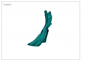
For example, one blade of a radial impeller (CAD geometry created by staff at PADT) is shown below. The sector was created such that the blades lie in the sector.
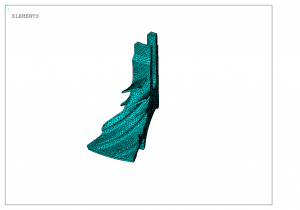
Below is the same radial impeller, but this time, cut with straight planes (which may be easier for some users, depending on the CAD software and how the geometry was created):
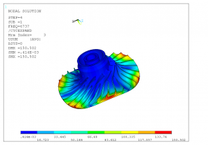
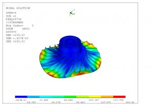
How does this affect accuracy? As the results below show, the ‘straight-cut’ sector gives the same results as the sector created to retain the blade:
First model, 1st mode of 3rd harmonic, “expanded” results:
Second model, 1st mode of 3rd harmonic, “expanded” results:
It’s useful to note that, in Workbench Mechanical (formerly Workbench Simulation), “Match Control” allows users to create a matching mesh on the ‘low’ and ‘high’ sides. (This feature is present in Workbench 10.0, 11.0, or 12.0. In previous revisions, it may be called “Match Face” mesh control.) Consequently, a user can do all of the pre-processing in Workbench Mechanical (Simulation). Only a few APDL commands are needed to have the solver perform cyclic symmetry analyses:
/PREP7
CYCLIC
/SOLU
An optional command is CYCOPT to specify additional parameters.
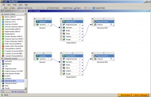
Once the model is set up and solved, one must postprocess in Mechanical APDL (formerly ANSYS). This is because Workbench Mechanical does not recognize the duplicate sectors that are created with the cyclic symmetry method. Doing this in Workbench 12.0 is quite straightforward, however; link a “Mechanical APDL” system to the Solution cell, as shown below, and the results can be opened and postprocessed easily in Mechanical APDL (use the /CYCEXPAND,1,ON command to see the full model):


Hi,
Thanks for the tips, they help me a lot.
I’m trying to model a rotor with two different sectors. Is it possible in Workbench, or Ansys Mechanical, at all?
You would need to model the smallest ‘common’ sector for such a case.
Thank you, that’s what I suspected.