Creating 3D cracks for fracture mechanics
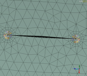
Added an example on ansys.net to create 3D penny-shaped crack using DesignModeler and meshing via Workbench Mechanical.
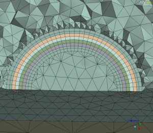
In DesignModeler, use of sweep or revolve tools allows one to generate the crack front geometry. In Workbench Meshing, use of Inflation Layers makes meshing the surrounding ‘rings’ of elements for the domain integral method quite easy, as shown below:
Even though inflation layers are typically associated with CFD applications, these can be useful in fracture mechanics as well as electromagnetic applications.
A key to ensure that good results are obtained is to use a Slice Plane to look inside of the mesh. The rings should all be generated in an outward manner, as shown below:
If the mesh is such that the ‘rings’ are not uniformly expanding, the J-integral results will show erratic values.
Note in this example that both (a) a ‘ring’ geometry to sweep-mesh hexes and (b) inflation layers are present. The swept mesh in the outer geometry is only 1 element thick with about 5 inflation layers.
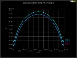
The J-integral results are shown below. Notice that contours #2 (outer swept-mesh ‘ring’ geometry) and #3-4 (inflation layers) show the same results, indicating that the use of inflation layers may be sufficient. (In other words, you do not have to create an outer ‘ring’ geometry as this example shows but may choose to rely on inflation layer meshing to produce the outer contour results.) Also, more elements could be used for contour evaluation — I just used a coarse mesh for this demonstration.
I also uploaded two 2D fracture mechanics models based on VM256 and VM267 on ansys.net.


Comments are closed.